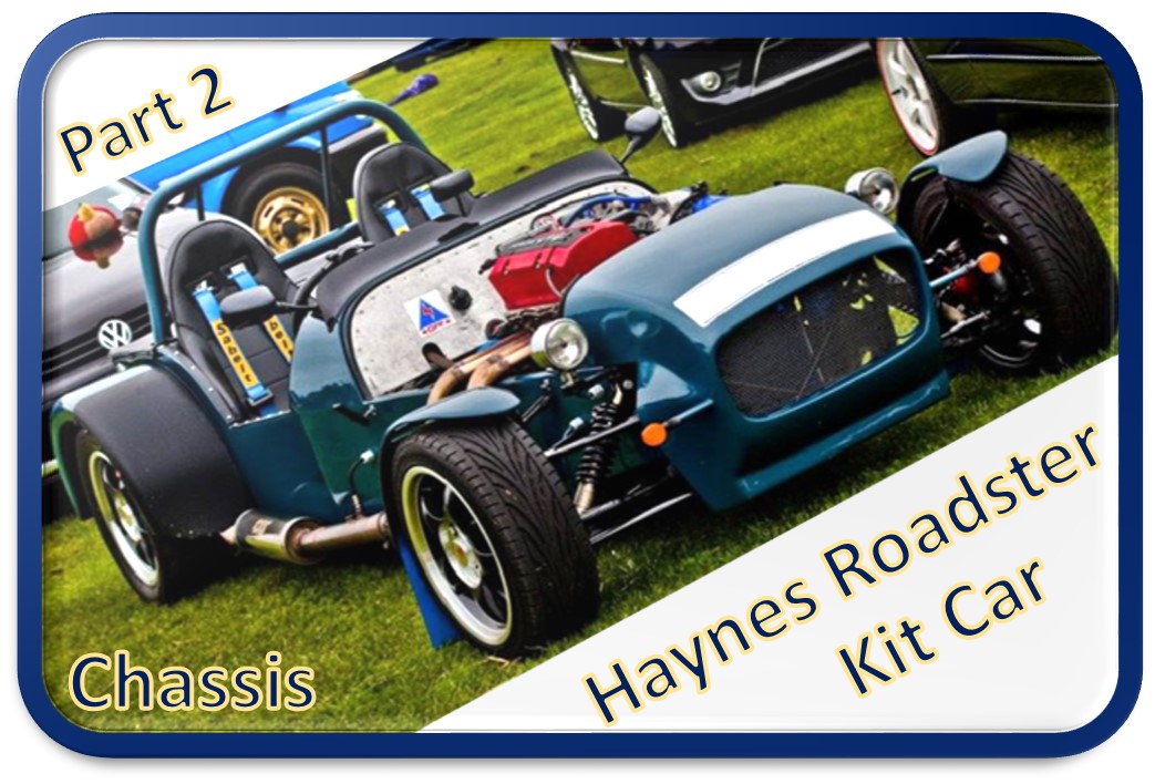
Welcome to part 2 of the Haynes Roadster build diary in this section we will be talking about how the chassis was built.
The chassis of the Haynes Roadster like almost all other cars of this type is a relatively simple steel space frame clad in aluminium and fibreglass panels.
The spaceframe has a mass of roughly 75Kg which when you consider this is the main bulk of the car is pretty darn light weight.
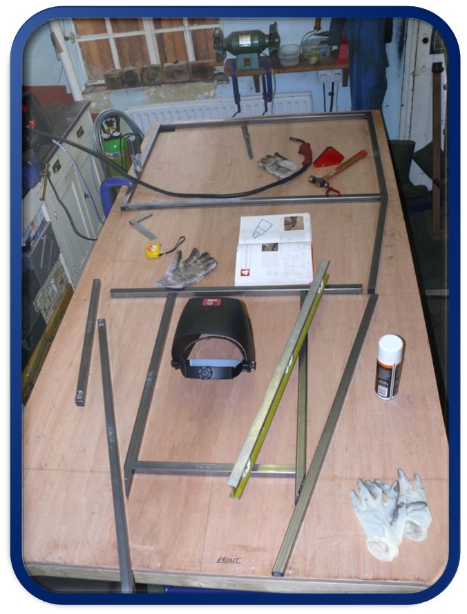
Before getting stuck in with the grinder and the welder a flat surface to layout the chassis on was required. For this a sheet of 18mm plywood screwed to a 50mm x 50mm timber frame was constructed and levelled on two trestles. Onto this table the bottom chassis tubes were laid out and tacked together. The chassis was welded using a 165Amp MIG welder with 1mm filler wire.
Once the bottom tubes were tacked and checked for square the side and top tubes could begin to be added. All the tubes were tacked together before any were fully welded this was so the structure could brace against itself during the welding process to help minimise any distortion.
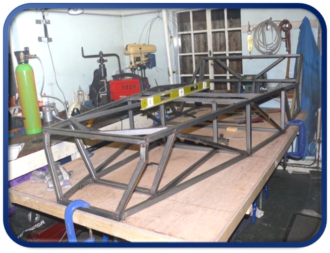
Once the front portion of the chassis was all tacked together the chassis was slid forward on the table so the rear frame could be attached. Yes the table was too short, you would have thought someone capable of building a car would have considered that before they started…
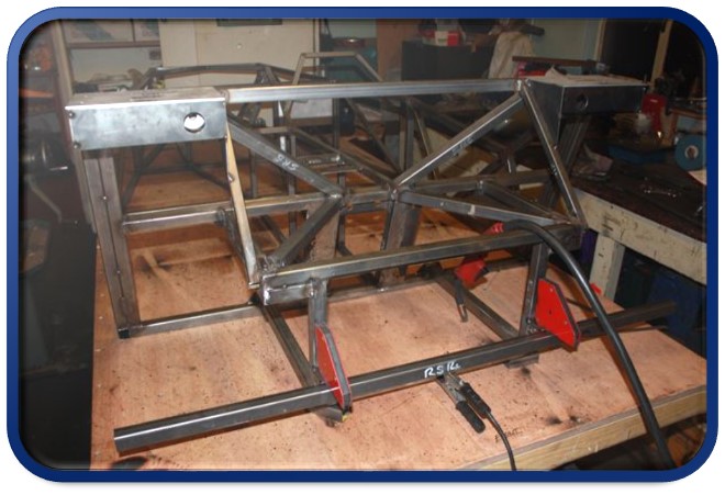
The rear section of the chassis has to be very strong and stiff as it houses the differential which it taking the rotation of the prop shaft, turns it through 90 degrees and passes this rotation via the half shafts to the wheels and in doing so is trying to twist the chassis like a pretzel. You can see in the picture below that there is a significant amount more reinforcement in this area.
Once the chassis was all tacked together it was time for the long and tedious process of completing the welding. To further help prevent the chassis from distorting the chassis was welded by first doing a weld on right hand side then doing the same weld on the left side. This back and forth pattern was used for every symmetrical weld on the chassis. The whole process took about a day to complete.
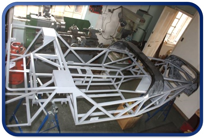
With the chassis fully welded the suspension mounts could be added. The reason not to add them before is to ensure there accurate location with respect to each other. If they were attached to the chassis before the chassis was welded any distortion would result in the suspension mounts being in the wrong place. By doing it this way the distortion has already occurred and the suspension mounts can be accurately located.
With all of the suspension mounts and other ancillary brackets attached the chassis was given a coat of 2 pack etching primer. A couple of points to note here. 2 pack paint is seriously bad for your health. I thought since I was applying it with a brush rather than spraying it I could just get away with opening the windows and not wearing a respirator. WRONG!!! Please learn from my mistake I am now highly sensitised to 2 pack paint and just the slightest whiff of the stuff can make me feel very lightheaded and give me some very uncomfortable chest pains. Please heed this advice; always use the proper protective equipment when using paints and solvents!